Sales: +971 55 541 5892 | sales@bravosatcom.com

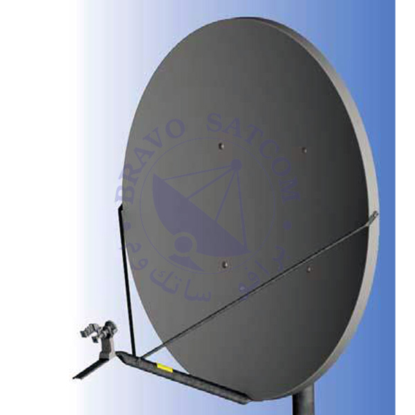
نظام هوائي استقبال/إرسال بحجم 1.8 متر، الفئة II، النوع 182، Global Skyware
- One piece thermoset-molded offset reflector
- Plated hardware for maximum corrosion resistance
- Pre-galvanized Construction
- 500 hour salt spray hardware
Product Specification
- One-piece thermoset-molded offset reflector: This suggests that the reflector is made from a single piece of thermoset-molded material. Thermoset refers to a type of plastic that, once set, cannot be melted or reshaped. The “offset” design indicates that the reflector is not a standard symmetrical shape but is positioned or shaped in a way that serves a specific purpose, often related to optimizing light distribution.
- Plated hardware for maximum corrosion resistance: The hardware, which includes nuts, bolts, screws, etc., is plated with a corrosion-resistant material. Plating helps protect the metal from corrosion caused by exposure to elements such as moisture, air, or chemicals.
- Pre-galvanized construction: This indicates that the construction material, likely steel, has been galvanized before the final product is manufactured. Galvanization involves coating the steel with a layer of zinc to protect it from corrosion.
- 500-hour salt spray hardware: The hardware has undergone a salt spray test for 500 hours. This test is a common method to evaluate the corrosion resistance of materials and surface coatings. It simulates the corrosive effects that can occur in a salt-laden environment, such as coastal areas.
Antenna Mechanical and Environmental Specifications
| Specifications | Details |
|---|---|
| Reflector Material | Glass Fiber Reinforced Polyester |
| Antenna Optics | One-Piece Offset Feed Prime Focus |
| Mount Type | Elevation over Azimuth |
| Maximum Radio Weight | 3.6 kg or 8 lb for RF Electronics |
| Elevation Adjustment Range | 10° – 90° Continuous Fine Adjustment |
| Azimuth Adjustment Range | 360° Continuous, ±10° Fine |
| Mast Pipe Interface | 114 mm (4.50 in) Diameter or 101 mm (4.00 in) Diameter |
| Wind Loading | Operational: 80 km/h (50 mph) |
| Survival: 200 km/h (125 mph) | |
| Temperature | -50°C to 80°C |
| Humidity | 0 to 100% (Condensing) |
| Atmosphere | Standard Hardware Meets 500 Hour Salt Spray Test Requirements (ASTM B-117) |
| Solar Radiation | 360 BTU/h/ft2 |
| Shock and Vibration | As Encountered During Shipping and Handlin |
C-Band & Ku-Band Antenna Specifications
| Specifications | C-Band | Ku-Band |
|---|---|---|
| Effective Aperture | 1.8m (71 in) | 1.8m (71 in) |
| Operating Frequency | Tx: 5.850 – 6.725 GHz | Tx: 13.75 – 14.50 GHz |
| Rx: 3.400 – 4.200 GHz | Rx: 10.70 – 12.75 GHz | |
| Polarization | Linear, Orthogonal | Linear, Orthogonal |
| Gain (±0.2 dBi) | Tx: 39.3 dBi @ 6.1 GHz | Tx: 46.8 dBi @ 14.3 GHz |
| Rx: 35.4 dBi @ 3.9 GHz | Rx: 45.3 dBi @ 12.0 GHz | |
| 3dB Beamwidth | Tx: 2.0° @ 6.1 GHz | Tx: 0.8° @ 14.3 GHz |
| Rx: 3.0° @ 3.9 GHz | Rx: 1.0° @ 12.0 GHz | |
| Sidelobe Envelope (Tx, Co-Pol dBi) | Mainbeam < Θ < 20°: 29 – 25 Log Θ | Mainbeam < Θ < 20°: 29 – 25 Log Θ |
| 20° < Θ 26.3°: -3.5 | 20° < Θ 26.3°: -3.5 | |
| 26.3° < Θ < 48°: 32-25 Log Θ | 26.3° < Θ < 48°: 32-25 Log Θ | |
| 48° < Θ < 180°: -10 | 48° < Θ < 180°: -10 | |
| Antenna Cross-Polarization | 30 dB on Axis | 30 dB on Axis |
| Antenna Noise Temperature | 30° El: 33°K | 30° El: 23°K |
| VSWR | Tx: 1.3:1 | Tx: 1.3:1 |
| Rx: 1.4:1 | Rx: 1.5:1 | |
| Isolation (Port to Port) | Tx: 60 dB | Tx: 80 dB |
| Rx: 60 dB | Rx: 35 dB | |
| Feed Interface | Tx: CPR-137 or Type N | Tx: WR75 Flat Flange |
| Rx: CPR-229 | Rx: WR75 Flat Flange |