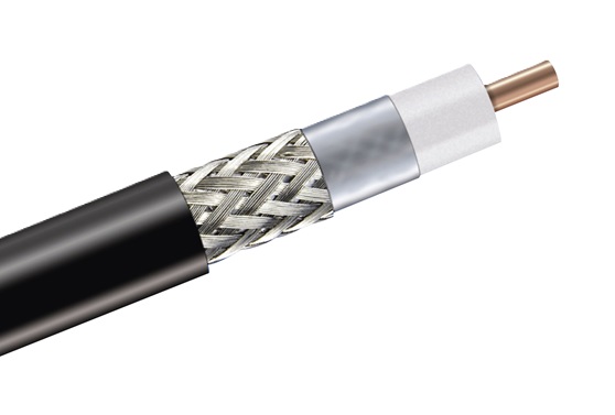

Tag Archives: COAXIAL CABLE

Fiber Optic vs Coaxial Cable: Key Differences, Uses & Which to Choose

When planning a satellite, VSAT, or telecom installation, one of the first decisions you face is cable type. Fiber optic and coaxial cable both carry signals from point A to point B — but they work in completely different ways, and choosing the wrong one means poor performance, expensive rework, or a system that won’t scale.

This guide breaks down everything you need to know: how each cable works, where each excels, and how to make the right call for your specific project.

Cross-section diagram comparing the internal layers of coaxial cable (LMR-400) versus fiber optic cable (SMF OS2)
Left: Coaxial cable carries both RF signal and DC power through a copper center conductor. Right: Fiber optic cable carries light only — no DC power capability.

What Is Coaxial Cable?

Coaxial cable carries RF signals as electrical waves along a center copper conductor, insulated from a surrounding braid or foil shield by a dielectric foam core. The shield keeps the signal contained and reduces external interference. An outer PE or PVC jacket provides mechanical and weather protection.

In VSAT and satellite applications the most common types are LMR-400 (standard Ku-band IFL, runs to ~30m), LMR-600 (medium runs to ~60m), LMR-900 (long runs to 80m+), and legacy RG-214. For broadcast and CATV distribution, 75Ω RG-6 is standard.

The capability that makes coaxial indispensable for satellite work: it carries DC power alongside the RF signal. The same cable that carries your IF signal from modem to LNB also delivers the 13V or 18V DC that powers the LNB — plus the 22 kHz polarisation tone — and the 24–48V DC that drives the BUC. No other single cable can do this.

What Is Fiber Optic Cable?

Fiber optic cable carries signals as pulses of light through a glass core, surrounded by cladding (a lower-refractive-index glass layer that traps light inside by total internal reflection), a protective buffer coating, and an outer jacket. There are no copper conductors — signals travel at the speed of light with virtually no attenuation over distance.

Two main types exist: single-mode fiber (SMF, OS1/OS2) for long-distance runs up to 40+ km, and multi-mode fiber (MMF, OM3/OM4) for shorter data links up to ~300–550m. For telecom backhaul and building-to-building links, SMF OS2 is the current standard.

The defining advantages: attenuation of just 0.2 dB/km at 1550 nm (versus approximately 6.6 dB/100m for LMR-400 at 1 GHz), complete immunity to electromagnetic interference, and effectively unlimited bandwidth. The defining limitation: fiber cannot carry DC power. Any powered equipment at the far end requires a separate power cable.


Signal Attenuation: The Numbers That Decide Everything

Signal loss — attenuation — is the single most important factor in cable selection. Here’s how the main cable types compare at 100 meters:

Bar chart showing signal attenuation per 100 meters for fiber optic OS2, LMR-900, LMR-600, LMR-400, RG-6 and RG-58 cables at 1 GHz
Signal loss per 100m at 1 GHz. Fiber OS2 loses virtually nothing over any practical run. RG-58 and RG-6 are unsuitable for any professional RF application beyond short jumpers.

At Ku-band frequencies (12 GHz), coaxial losses are significantly higher still — LMR-400 loses approximately 30 dB per 100m at Ku-band, which is why VSAT IFL runs must be kept short or upgraded to larger cable (LMR-600 or LMR-900).


Fiber Optic vs Coaxial: Full Comparison

Feature Coaxial Cable (LMR-400) Fiber Optic (SMF OS2)
Signal mediumElectrical (RF waves)Light (photons)
Attenuation @ 1 GHz6.6 dB / 100m0.02 dB / 100m
Attenuation @ Ku-band (12 GHz)~30 dB / 100mN/A — not RF
Max VSAT IFL run (Ku-band)30m (LMR-400) · 60m (LMR-600) · 80m+ (LMR-900)Not suitable for IFL
Max data run (1 Gbps)~100m (Cat6 Ethernet)10+ km (SMF)
EMI immunityPartial — braid reduces, does not eliminateComplete — light is unaffected by EMI
DC power over cable✓ Yes — LNB 13/18V + BUC 24–48V✗ No — separate power cable required
RF signal (native)✓ Yes✗ No — requires optical conversion
BandwidthDC to 40 GHz (LMR-600)Practically unlimited (>100 THz)
Field terminationEasy — crimp tool + N-type / SMA / BNCRequires fusion splicer + cleaver
SecurityCan be passively tappedTap causes detectable signal loss
Ground loop / surge riskYes — copper conductorNone — glass is non-conductive
WeightHeavierVery light
Cable costLowerModerate to high
Equipment costLowerHigher (transceivers, media converters)
Typical connectorsN-type, F, BNC, SMA, TNCLC, SC, ST, FC

When to Use Coaxial Cable

✓ Coaxial is the right choice for:

VSAT and satellite IFL runs — Mandatory. Your satellite modem must deliver DC power to the LNB (13V/18V + 22 kHz polarisation tone) and BUC (24–48V) through the same cable that carries the IF signal. Use LMR-400 up to 30m, LMR-600 to 60m, LMR-900 to 80m+ at Ku-band.

Antenna feedlines — VHF/UHF, cellular base station, and microwave antenna connections are always coaxial. LMR-400 is the standard for fixed base station feedlines; LMR-600 for tower runs over 20m.

RF signal distribution — Splitters, combiners, amplifiers, RF patch panels: anywhere you’re routing a live RF signal, coaxial connections are required throughout the chain.

CCTV and analog video — Analog camera systems (HD-CVI, TVI, AHD) use RG-59 or RG-6. Still widely deployed throughout the GCC due to existing cable infrastructure.

Remote DC power delivery — Any equipment that needs power over the cable (BUC on a tower, LNB on a dish) requires coaxial IFL. There is no alternative.

Field installations — Coax connectors are field-terminable with a hex crimp tool. Fiber fusion splicing requires capital equipment and a clean environment — coax wins on field flexibility every time.

When to Use Fiber Optic Cable

✓ Fiber optic is the right choice for:

Long data backbone runs (>100m) — Any network link over 100 meters at Gigabit speeds or higher should be fiber. SMF supports 10G Ethernet over 10+ km without amplifiers.

Building-to-building links — Outdoor aerial or buried runs between buildings need fiber for ground-loop isolation and lightning surge protection. Copper cable between separate structures can conduct a surge that destroys equipment at both ends.

High-EMI environments — Generator rooms, industrial motor drives, high-voltage transformer enclosures: fiber is completely immune to electromagnetic interference regardless of the surrounding electrical noise.

High-bandwidth data (40G / 100G / 400G) — These speeds require fiber. Not achievable over coaxial cable at any practical distance.

Security-critical links — Fiber cannot be intercepted passively. Any physical tap causes a measurable signal loss that optical monitoring can detect and alert on.

Harsh or marine environments — Fiber is immune to salt air corrosion, moisture ingress effects on signal quality, and temperature-driven impedance changes.


Why VSAT Always Uses Coaxial — Without Exception

Diagram showing a VSAT installation with coaxial IFL cable between the outdoor unit and satellite modem, and fiber optic or Cat6 cable between the modem and office network
In a VSAT installation, coaxial cable (LMR-400/600/900) is mandatory for the IFL between the outdoor unit and modem — it carries both the RF signal and DC power to the BUC and LNB. Fiber or Cat6 handles the IP data backbone from modem to the office network.

In any VSAT installation — from a single maritime terminal to a large teleport earth station — the IFL between the satellite modem and the outdoor unit must be coaxial cable. The reason is simple: the modem or ODU controller delivers DC power to the LNB and BUC through the same coaxial IFL that carries the IF signal. Fiber optic cable cannot carry DC power.

Fiber-based IF extension systems do exist. They use optical modulators and demodulators with separate power injectors to extend IFL runs beyond 100 meters in large earth station facilities. But these are expensive, complex installations reserved for sites where very long cable runs make standard coax impractical. For any typical VSAT site, coaxial cable is the correct and only practical IFL solution.

See also: LMR-400 vs LMR-600: Which Should You Choose?


Frequently Asked Questions

Can I replace my VSAT coaxial IFL with fiber optic cable?
Not without additional equipment. The BUC and LNB require DC power that can only be delivered over coaxial cable in a standard installation. Fiber-based IF extension systems exist for very long runs (>100m) in large facilities, but they require optical modulators and separate power injectors — significant cost and complexity. For any typical VSAT installation, coaxial cable is the correct IFL choice.
Which has less signal loss — fiber optic or coaxial?
Fiber wins by a dramatic margin for data. LMR-400 loses approximately 6.6 dB per 100 meters at 1 GHz — and ~30 dB per 100m at Ku-band (12 GHz). Single-mode fiber OS2 loses just 0.2 dB per kilometer at 1550 nm. Over a 100m run, fiber loses roughly 0.02 dB versus LMR-400’s 6.6 dB — about 330× less attenuation. However, this comparison only applies to data signals. For native RF signals (satellite IF, antenna feedlines), there is no “fiber alternative” without conversion equipment.
Is fiber optic cable more expensive than coaxial?
Fiber cable typically costs more per meter, and field termination requires a fusion splicer — significant capital equipment. However, for long data backbone runs where coax would require inline amplifiers or multiple segments, fiber often becomes cost-competitive overall. For short RF applications under 50 meters, coaxial cable is almost always the lower-cost total solution.
Can fiber optic cable be used as an antenna feedline?
No — not without conversion equipment. Fiber carries light signals, not analog RF. An antenna feedline must be coaxial to carry the raw RF signal between the antenna and the radio or satellite modem. Any fiber in an RF path requires RF-to-optical conversion at both ends, adding cost and complexity that makes it impractical for standard installations.
What coaxial cable should I use for Ku-band VSAT?
Use LMR-400 for IFL runs up to 30 meters at Ku-band, LMR-600 for 30–60 meters, and LMR-900 for runs beyond 60 meters. All outdoor sections should use weatherproof N-type connectors with proper sealing tape. Never use RG-6 or RG-58 for VSAT — their attenuation at Ku-band is far too high even for short runs.

Need coaxial cable for your VSAT or satellite installation?
BravoSatcom stocks LMR-400, LMR-600, LMR-900 and IFL cables. We ship across the GCC.
Shop Cables →

How to Crimp LMR Connectors Correctly: Step-by-Step Guide

A poorly terminated connector is the number one cause of signal degradation on an otherwise well-designed RF installation. LMR cables — particularly LMR-400 — are used on VSAT IFL runs, radio base station feedlines, and outdoor antenna installations where the connector is exposed to weather, vibration, and long-term stress. Getting the crimp right the first time saves you a troubleshooting call six months later.

This guide walks through the complete termination process for LMR-400 with an N-type crimp connector — the most common combination in VSAT and radio work — and covers the critical dimensions, tools, and mistakes that separate a reliable termination from a future fault.

LMR-400 Cable Preparation — Strip Stages

Jacket
Full length
Braid exposed
25.4 mm
(fold back)
Dielectric
12.7 mm
(stripped)
Centre pin
12.7 mm
exposed
Outer jacket (PE)
Braid + foil shield
Foam PE dielectric
Copper centre conductor

LMR-400 N-type crimp | Dimensions per Times Microwave spec | bravosatcom.com

What You’ll Need

Getting the right tools matters more than most people realise. Undersized or worn tooling causes crimp failures that are invisible to the eye but catastrophic for RF performance.

ToolPurposeNotes
Coax cable cutterClean, square cable cutNever use wire cutters or a hacksaw — both distort the cable end
Rotary coax stripperStrip jacket, braid, dielectric to exact dimensionsSet blade depths for LMR-400 specifically
Hex crimp tool + dieCompress ferrule onto braidLMR-400 N-type typically requires 0.429″ hex die — check connector spec
Utility knife / deburring toolClean dielectric end, remove stray braid strands
Vernier calipersVerify strip dimensionsOptional but recommended for critical installs
MultimeterPost-crimp continuity testMandatory before putting the cable into service
Connector types: This guide covers crimp connectors — the most common in field work. Times Microwave also makes EZ-400 compression connectors (faster, single-action, requires the matching tool) and solder-type connectors. The cable prep dimensions are similar but confirm against your specific connector’s installation sheet.

Strip Dimensions for LMR-400 N-Type Crimp

These are the published Times Microwave strip dimensions for LMR-400 with a standard N-type crimp connector. Write these on your tool bag if you do this regularly.

StripDimensionWhat It Exposes
Outer jacket removal25.4 mm (1.00″)Braid for fold-back
Braid fold-back point12.7 mm (0.50″) from jacket endPositions braid over ferrule
Dielectric removal12.7 mm (0.50″) from fold pointCentre conductor
Centre conductor trimFlush with connector pin faceClean mating contact
Dimensions vary between connector manufacturers. Always cross-check against your specific connector’s installation sheet before terminating.

Step-by-Step: N-Type Crimp on LMR-400

1
Cut the cable square. Use a proper coax cutter. The cut must be clean, flat, and perpendicular. Inspect: jacket, braid, dielectric, and centre conductor must all be concentric and undamaged. Any burr or angle — cut again.
2
Slide on the crimp ferrule first. Before stripping anything, slide the crimp ferrule (small metal ring) onto the cable with the open end facing the cable end. This is the most commonly forgotten step. You cannot install it after the connector body is on.
3
Strip the outer jacket — 25.4 mm. Set your rotary stripper and rotate 2–3 times, then pull the jacket off cleanly. Inspect the braid — intact, no nicks, no cut strands. Remove any cut braid strands before proceeding.
4
Fold back the braid — at 12.7 mm. Comb the braid wires back evenly over the outer jacket. Spread uniformly around the full circumference — avoid bunching. Bunched braid concentrates crimp force on one side and reduces shield effectiveness.
5
Strip the dielectric — 12.7 mm. Remove foam dielectric to expose the centre conductor. The cut must be clean — no gouges or teeth marks on the copper. Even minor nicks increase PIM and create stress crack points under vibration.
6
Inspect before assembly. Blow out loose strands. Verify strip dimensions. Confirm no braid strands are on the dielectric. Check the centre conductor is round and undamaged. A 30-second inspection here prevents a re-termination in the field.
7
Install the connector body. Slide the connector body onto the cable. The centre conductor passes through the contact pin and protrudes slightly — trim flush with the pin face. The braid seats inside the connector’s braid seat area. Push fully home until it seats firmly.
8
Slide the ferrule into position. Slide the crimp ferrule forward until it butts against the rear of the connector body, sitting over the folded braid.
9
Crimp. Place the ferrule in the correct hex die. Close the handles with a single smooth, firm stroke until the ratchet releases. One complete ratchet cycle only — do not over-crimp (distorts the body) or under-crimp (ferrule slips).
10
Inspect the finished crimp. The ferrule should be uniformly hexagonal, no cracking or oval distortion. Firm tug — connector should not move. No braid strands protruding. Centre pin flush or just proud of the mating face.

Common Mistakes

MistakeConsequenceFix
Forgetting the ferrule before assemblyMust cut off connector and restartSlide ferrule on as Step 2, every time
Nicked centre conductorPIM, cracking under vibration, future openRe-cut cable end and re-terminate
Stray braid strands on dielectricDead short centre-to-outerInspect under good light before inserting body
Wrong hex die sizeUnder-crimp — passes pull test, fails in fieldAlways match die to connector spec sheet
Bunched braid foldNon-uniform crimp, reduced shield coverageComb braid evenly around full circumference
Centre pin too longBottoms out in mating connector, damages bothTrim flush with pin face
RG-8 connector on LMR-400Wrong bore — mechanically and electrically poorAlways use connectors specified for LMR-400

Testing Your Termination

Every terminated connector should pass three checks before the cable goes into service:

① Visual Inspection
Ferrule uniformly hexagonal. No braid strands protruding. Centre pin flush. Connector firmly seated — no movement under hand tug.
② DC Continuity (Multimeter)
Centre pin to centre pin: continuity. Centre pin to outer body: open circuit. Any short = failed termination, re-terminate.
③ Return Loss / VSWR (if available)
Good LMR-400 termination: >25 dB return loss (VSWR <1.12:1) at 1 GHz. Worse than 20 dB (VSWR >1.22:1) indicates a problem.

Connector Compatibility Quick Reference

Always match the connector spec to your cable. Using an LMR-400 connector on LMR-600 is the most common ordering mistake.

LMR CableStandard ConnectorCrimp Die (typical)Notes
LMR-195N-type, SMA, BNCPer connector specCheck braid OD matches
LMR-240N-type, SMAPer connector spec
LMR-400N-type0.429″ hex (typical)Standard VSAT IFL
LMR-600N-type, 7/16 DINDifferent bodyDo NOT mix with LMR-400 connectors
LMR-900N-type, 7/16 DINLarge-body only7/16 DIN preferred for high power

For a full cable series comparison, see the Times Microwave LMR Series guide.

FAQ

Can I reuse an LMR connector after removing it?
No. Once a crimp ferrule has been compressed, it cannot be re-used. Cut the connector off, re-prepare the cable end, and use a new connector.

What’s the minimum pull-out force for a properly crimped LMR-400 connector?
Times Microwave specifies approximately 45 kg (100 lbs) minimum pull-out strength for a correctly crimped LMR-400 N-type. If yours pulls off with hand force, the crimp failed.

Can I use a standard N-type connector meant for RG-8 on LMR-400?
No. LMR-400 has a different OD, braid construction, and dielectric. Using an RG-8 connector produces a mechanically and electrically poor termination. Always specify connectors made for LMR-400.

How do I know if my crimp tool die is worn?
A worn die produces ferrules that are out-of-round or show uneven hex faces. Check with calipers — if in doubt, replace the die. A worn die is cheaper to replace than a failed installation.

What’s the difference between silver and gold centre pins?
Silver-plated pins are standard for VSAT work. Gold pins appear in some lower-frequency or high-reliability connectors. For LMR-400 N-type in VSAT IFL work, silver-plated is correct.

Need LMR Cables and Connectors?

Bravo Satcom supplies Times Microwave LMR cables and N-type connectors for VSAT and radio installations across the UAE and GCC. We stock LMR-240, LMR-400, and LMR-600 with matching crimp and compression connectors.

→ Browse cable products    → Request a quote

Fiber Optic vs Coaxial Cable: When to Use Each

Every RF and satellite engineer hits this fork eventually: you’re designing a cable run and someone asks, “should we go fiber?” The right answer depends almost entirely on what the cable is carrying. If it’s connecting a modem to a BUC or LNB, the answer is always coaxial — no exceptions. If it’s a data backbone between buildings, fiber is almost certainly the better call.

This guide breaks down the key differences between fiber optic and coaxial cable and gives you a clear framework for choosing the right one every time.

COAXIAL CABLE (LMR-400) 50Ω · RF + DC Power Center Conductor (Cu) Dielectric Foam Braid Shield Outer Jacket (PE/PVC) ✓ RF Signal + DC Power (BUC / LNB) FIBER OPTIC CABLE (SMF OS2) Single-Mode · Light Signal Only Glass Core (9 µm) Cladding (125 µm) Buffer Coating Outer Jacket (LSZH / PE) ✗ Light Signal Only — No DC Power
Fig 1. Cable cross-section comparison: coaxial (LMR-400) vs single-mode fiber optic (SMF OS2). The critical difference for VSAT installations — coaxial cable carries DC power to the BUC and LNB alongside the RF signal; fiber cannot.

What Is Coaxial Cable?

Coaxial cable carries RF signals as electrical waves along a center copper conductor, insulated from a surrounding braid or foil shield by a dielectric foam core. The shield keeps the signal contained and blocks external interference from entering. An outer PE or PVC jacket provides mechanical and weather protection.

In VSAT and satellite applications the most common types are LMR-400 (standard Ku-band IFL, runs to ~30m), LMR-600 (medium runs to ~60m), LMR-900 (long runs to 80m+), and legacy RG214. For broadcast and CATV distribution, 75Ω RG6 is common.

The capability that makes coaxial indispensable for satellite work: it carries DC power alongside the RF signal. The same cable that carries your IF signal from modem to LNB also delivers the 13V or 18V DC that powers the LNB — plus the 22 kHz polarisation tone — and the 24–48V DC that drives the BUC. No other single cable can do this.

What Is Fiber Optic Cable?

Fiber optic cable carries signals as pulses of light through a glass core, surrounded by cladding (a lower-refractive-index glass layer that traps light inside by total internal reflection), a protective buffer coating, and an outer jacket. There are no copper conductors — signals travel at the speed of light with virtually no attenuation over distance.

Two main types exist: single-mode fiber (SMF, OS1/OS2) for long-distance runs up to 40+ km, and multi-mode fiber (MMF, OM3/OM4) for shorter data links up to ~300m. For telecom and data center backbone, SMF OS2 is the current standard.

The defining advantages: attenuation of just 0.2 dB/km at 1550 nm (vs approximately 30 dB/100m for LMR-400 at Ku-band), complete immunity to electromagnetic interference, and effectively unlimited bandwidth. The defining limitation: fiber cannot carry DC power. Any powered equipment at the far end requires a separate power cable.

Fiber Optic vs Coaxial Cable: Full Comparison

Feature Coaxial Cable (LMR-400) Fiber Optic (SMF OS2)
Signal medium Electrical (RF waves) Light (photons)
Attenuation @ 1 GHz 6.8 dB / 100m 0.035 dB / 100m
Attenuation @ Ku-band (12 GHz) ~30 dB / 100m N/A — light, not RF
Max practical IFL run (Ku-band) 30m (LMR-400) · 60m (LMR-600) · 80m (LMR-900) Not suitable for IFL
Max data run ~50m (10GBaseT, Cat6A) 40+ km (SMF)
EMI immunity Partial (braid reduces, does not eliminate) Complete — immune to all EMI
DC power over cable ✓ Yes — LNB 13/18V, BUC 24–48V ✗ No — separate power cable required
RF signal (native) ✓ Yes ✗ No — requires RF-to-optical conversion
Bandwidth DC to 40 GHz (LMR-600) Practically unlimited (>100 THz)
Field termination Easy — crimp tool, N-type / SMA / BNC Requires fusion splicer + cleaver
Cable cost Lower Higher
Weight Heavier Very light
Minimum bend radius 25mm (LMR-400) 30mm (standard OS2)
Security Can be passively tapped Tap causes detectable signal loss
Ground loop / surge risk Yes — copper conductor None — glass is non-conductive

When to Use Coaxial Cable

✓ Coaxial is the right choice for:

1. VSAT and satellite IFL runs — Mandatory. Your satellite modem must deliver DC power to the LNB (13V/18V + 22 kHz polarisation tone) and BUC (24–48V) through the same cable that carries the IF signal. Use LMR-400 up to 30m, LMR-600 to 60m, LMR-900 to 80m+ at Ku-band.

2. Two-way radio and base station antenna feedlines — VHF/UHF antenna connections are always coaxial. LMR-400 is the standard for fixed base station installations.

3. RF signal distribution — Splitters, combiners, amplifiers, RF patch panels: anywhere you’re routing or processing a live RF signal, coaxial connections are required throughout the chain.

4. Short runs under 40–50 meters — For L-band and below, coax is simpler, cheaper, and easier to terminate. The attenuation penalty is manageable for short runs.

5. Remote RF power delivery — Any equipment at the far end that needs power over the cable (BUC on a tower, LNB on a dish) requires coaxial IFL — there is no alternative.

6. Field installations — Coax connectors (N-type, SMA, TNC, BNC) are field-terminable with a hex crimp tool. Fusion splicing fiber requires capital equipment and a clean environment.

When to Use Fiber Optic Cable

✓ Fiber optic is the right choice for:

1. Long data backbone runs (>100m) — Any Ethernet or network backbone link over 100m should be fiber. SMF supports 10G Ethernet over 10+ km without amplifiers. Coaxial cable would require impractically thick gauge (LMR-900+) and still fall short.

2. EMI-heavy environments — Generator rooms, industrial motor drives, high-voltage transformer enclosures: fiber is completely immune. Coax braid reduces EMI pickup but does not eliminate it — you’ll see interference on the signal.

3. Building-to-building links — Outdoor aerial or buried runs between buildings: fiber provides natural ground-loop isolation and is immune to lightning surges between structures. Copper cable between buildings can conduct a surge that damages equipment at both ends.

4. High-bandwidth data (40G / 100G / 400G) — These speeds are not achievable over coaxial cable at practical distances. Fiber is the only option.

5. Security-critical installations — Fiber signals cannot be intercepted passively. Any physical tap causes a measurable signal loss that optical monitoring equipment can detect and alert on.

6. Harsh or marine environments — Fiber is immune to moisture ingress effects on signal quality, salt air corrosion of conductors, and temperature-driven changes in impedance.

Why VSAT Always Uses Coaxial — Without Exception

In any VSAT installation — from a single maritime terminal to a large teleport earth station — the IFL between the satellite modem and the outdoor unit (BUC and LNB) must be coaxial cable. The reason is simple: the satellite modem or ODU controller delivers DC power to the LNB and BUC through the same coaxial IFL that carries the IF signal. Fiber optic cable cannot carry DC power.

Fiber-based IF extension systems do exist. They use optical modulators and demodulators with separate power injectors to extend IFL runs beyond 100 meters in large earth station facilities. But these are expensive, complex installations reserved for sites where very long cable runs make standard coax impractical. For any typical VSAT site — from a rooftop dish to a teleport hub — coaxial cable (LMR-400 through LMR-900 depending on run length) is the only practical and cost-effective IFL solution.

See also: LMR-400 vs LMR-600: Which Should You Choose?

Frequently Asked Questions

Can I replace my VSAT coaxial IFL with fiber optic cable?
Not without additional equipment. The BUC and LNB require DC power that can only be delivered over coaxial cable in a standard installation. Fiber-based IF extension systems exist for very long runs (>100m) in large facilities — they use optical modulators with separate power injectors — but they are expensive and complex. For any typical VSAT installation, coaxial cable is the correct and only practical IFL choice.
Which has less signal loss — fiber optic or coaxial?
Fiber wins dramatically. LMR-400 loses approximately 30 dB per 100 meters at Ku-band (12 GHz). Single-mode fiber OS2 loses just 0.2 dB per kilometer at 1550 nm — roughly 15,000 times less attenuation per meter. For data signals over any meaningful distance, fiber is the clear choice.
Is fiber optic cable more expensive than coaxial?
Fiber cable typically costs more per meter, and termination requires a fusion splicer — significant capital equipment. However, for long runs where you’d otherwise need thick-gauge LMR-900 coax plus inline amplifiers, fiber can become cost-competitive overall. For short RF applications under 50 meters, coaxial cable is almost always the lower-cost total solution.
Can fiber optic cable be used as an antenna feedline?
No — not without conversion equipment. Fiber carries digitised optical signals, not analog RF. An antenna feedline must be coaxial to carry the raw RF signal between the antenna and the radio or satellite modem. Any fiber in an RF path requires RF-to-optical conversion at both ends, which adds cost and complexity that makes it impractical for standard installations.
What coaxial cable should I use for Ku-band VSAT IFL runs?
Use LMR-400 for IFL runs up to 30 meters at Ku-band, LMR-600 for 30–60 meters, and LMR-900 for runs beyond 60 meters. All outdoor sections should use weatherproof N-type connectors with proper weatherproofing tape. Never use RG6 or RG58 for VSAT — their attenuation at Ku-band is far too high even for short runs.

Need coaxial cable for your VSAT or satellite installation?
BravoSatcom stocks LMR-400, LMR-600, RG214 — weatherproof N-type connectors included.
We ship across the GCC.

Shop Coaxial Cable →

Navigating RF Alternatives: Beyond LMR-400

Exploring Alternatives to LMR-400 Coaxial Cable


Hey folks, welcome to the blog – your hub for all things tech. Today, we’re diving deep into the world of coaxial cables, specifically looking beyond the widely acclaimed LMR-400. If you’re knee-deep in wireless communications or RF applications, stick around because this is about to get interesting.

The Story of LMR-400:

LMR-400 has its own chapter in the book of coaxial cables, celebrated for its low-loss characteristics that make it the go-to for various RF applications. But here’s the kicker – did you know there are other cables out there that could give it a run for its money? Let’s unpack this.


Alternative 1:  – The Flexible Contender:

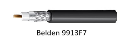
First up in our lineup is the Belden 9913F7. Think of it as the LMR-400’s flexible cousin. This coaxial cable not only bends but also flexes its muscles in the realm of low-loss performance, making it a top pick for many RF enthusiasts looking for a solid alternative.

Belden 9913F7

Alternative 2: Times Microwave Systems LMR-400 UltraFlex – Flexibility Redefined:

Now, picture this – a more flexible version of the already impressive LMR-400. Enter the Times Microwave Systems LMR-400 UltraFlex. It’s like getting the best of both worlds – maintaining stellar performance while offering increased flexibility. Perfect for those situations where flexibility is not just a preference but a necessity.


Alternative 3: Andrew CNT-400 – The Reliable Choice:

Moving down the list, we have the Andrew CNT-400. Born out of the CommScope legacy, this coaxial cable is a reliable choice for RF applications, standing shoulder to shoulder with the LMR-400 in terms of performance. It’s like the dependable friend you can always count on.

Alternative 4: RG-213 – The Unconventional Contender:

Last but certainly not least is the RG-213. While not an identical twin to the LMR-400, it plays the part of the unconventional contender. With similar characteristics and just a touch more loss, RG-213 might be the wildcard that suits your specific needs.

So, there you have it – a lineup of alternatives that might just make you reconsider your go-to coaxial cable. When you’re deep in the world of RF, every choice matters, and it’s essential to consider factors like attenuation, flexibility, and compatibility with your equipment.

Feel free to explore these alternatives based on your specific requirements. The coaxial cable you choose could be the unsung hero behind seamless RF communications. Until next time, tech enthusiasts – stay curious, stay connected!

Understanding LMR400 Loss: What You Need to Know

If you’re looking for a high-quality coaxial cable, you might have heard about LMR400. It’s a popular choice for a variety of applications, including Wi-Fi and cellular networks, amateur radio, and more. But one of the most important considerations when selecting a coaxial cable is the loss, or attenuation, that occurs as the signal travels through the cable. In this post, we’ll discuss LMR400 loss and what you need to know to make an informed decision.

What is LMR400?

LMR400 is a type of coaxial cable that has a solid copper center conductor, foam polyethylene insulation, and dual shielding consisting of a bonded aluminum foil and a tinned copper braid. The cable has a diameter of 0.405 inches (10.3 mm) and a 50-ohm impedance, which is the standard impedance for most RF applications. LMR400 is designed for low-loss applications and has a nominal attenuation of 6.6 dB per 100 feet (30 m) at 900 MHz.

LMR400 Loss: How Much Attenuation Occurs?

As mentioned earlier, loss is one of the most important considerations when selecting a coaxial cable. It’s the amount of signal that’s lost as it travels through the cable due to various factors such as resistance, dielectric losses, and radiation. In the case of LMR400, the loss is relatively low compared to other types of coaxial cables. Here’s a table of comparison for LMR400 loss at different frequencies:

Frequency (MHz) Attenuation per 100 ft (dB)
10 0.4
50 1.1
100 1.6
400 3.9
900 6.6
1000 7.1
1500 9.3
2000 11.1
5800 24.4

As you can see, the attenuation increases as the frequency increases. This is due to the skin effect, which causes the signal to travel mainly on the surface of the conductor at higher frequencies, increasing the resistance and thus the loss.

Factors Affecting LMR400 Loss

The attenuation of LMR400 depends on several factors, including the length of the cable, the frequency of the signal, the temperature, and the installation method. For example, if the cable is kinked or bent too sharply, it can cause extra loss due to increased resistance. Likewise, if the cable is installed in an area with high temperatures, it can cause the insulation to break down, increasing the loss.

Conclusion

LMR400 is a popular coaxial cable for a variety of applications due to its low loss, high performance, and durability. When selecting a coaxial cable, it’s important to consider the attenuation or loss that occurs as the signal travels through the cable. The loss of LMR400 is relatively low compared to other types of coaxial cables, making it a great choice for long-distance and high-frequency applications. However, it’s also important to consider factors that can affect the loss, such as cable length, frequency, temperature, and installation method, to ensure optimal performance.

We hope this post has helped you understand LMR400 loss and what you need to know to make an informed decision. If you have any questions or comments, feel free to leave them below.

RF Cable or IF Cable? Know The Difference

RF stands for “radio frequency,” while IF stands for “intermediate frequency.” Both RF and IF cables are types of coaxial cables, which are used to transmit signals in electronic devices.

What are coaxial cables?

A coaxial cable is a type of cable that has a center conductor, surrounded by an insulating layer, which is then surrounded by a metallic shield. The metallic shield helps to protect the signal from interference and noise.

What are radio signals and intermediate frequency signals?

Radio signals are high-frequency signals that are used to transmit information wirelessly. For example, when you listen to the radio in your car, the radio station sends out radio signals that your car’s antenna picks up.

Intermediate frequency (IF) signals are lower-frequency signals that are used in electronic devices, such as radios and televisions. These signals are generated by mixing or combining two or more high-frequency signals to create a lower-frequency signal that is easier to process.

What are RF cables used for?

RF cables are used to connect antennas to electronic devices, such as radios, televisions, and wireless routers. These cables carry high-frequency radio signals from the antenna to the device, allowing you to receive and process the radio signal.

What are IF cables used for?

IF cables are used in electronic devices, such as radios and televisions, to connect different stages of the receiver or transceiver. These cables carry the intermediate frequency signals, which are easier to process than high-frequency radio signals.

What’s the difference between RF and IF cables?

The main difference between RF and IF cables is the type of signal they carry and where they are used in a device. RF cables are used to transmit high-frequency radio signals from an antenna to a device, while IF cables are used to connect different stages of a receiver or transceiver, carrying intermediate frequency signals.

Table comparing RF and IF cables:

  RF Cable IF Cable
Definition Used to connect antennas to electronic devices, carrying high-frequency radio signals Used to connect different stages of a receiver or transceiver, carrying intermediate frequency signals
Frequency Range High-frequency signals Lower-frequency signals
Application Used in radios, televisions, and wireless routers Used in radios and televisions
Signal Processing Used for receiving and processing radio signals Used for processing intermediate frequency signals


In summary, RF and IF cables are both types of coaxial cables that are used to transmit signals in electronic devices. While they may look similar, they have different uses and carry different types of signals.

RF cables are used to transmit high-frequency radio signals from an antenna to a device, while IF cables are used to connect different stages of a receiver or transceiver, carrying intermediate frequency signals.

TOP 5: Coaxial Cable Brands and Manufacturers

Coaxial cables are a type of cable that’s commonly used for transmitting high-frequency signals between electronic devices. They consist of an inner conductor surrounded by a dielectric insulator, which is in turn surrounded by an outer conductor, often in the form of a braided shield.

What makes coaxial cables special is their ability to maintain signal integrity over long distances. They’re able to do this because of their unique design, which helps prevent signal loss and interference. Here’s how it works:

The inner conductor carries the signal, which is often an electrical current or electromagnetic wave. The dielectric insulator separates the inner conductor from the outer conductor, which serves as a shield. The outer conductor helps prevent interference from external electromagnetic fields and also helps keep the signal from leaking out.

The quality of a coaxial cable is determined by various factors, such as its impedance, attenuation, shielding, and bandwidth. A higher-quality cable will have lower attenuation and higher shielding effectiveness, which means it can transmit signals over longer distances with less signal loss.

When it comes to coaxial cables, there are several manufacturers and brands to choose from. Here are some of the top ones:

  1. Belden Inc.
  2. CommScope Inc.
  3. Times Microwave Systems
  4. Amphenol RF
  5. RG-Coaxial

Belden Inc. is a leading manufacturer of high-performance coaxial cables used in various industries, including telecommunications, broadcast, and military. CommScope Inc. offers a variety of coaxial cables for different applications, such as wireless networks, broadband, and video surveillance. Times Microwave Systems specializes in manufacturing high-quality coaxial cables for military, aerospace, and commercial applications. Amphenol RF is a leading supplier of RF coaxial connectors and cables for various industries, including telecommunications, automotive, and medical. RG-Coaxial is a well-known brand of coaxial cables that are widely used in consumer electronics, such as TVs, radios, and antennas.

In conclusion, coaxial cables are an important part of modern electronics, allowing for the transmission of high-frequency signals over long distances with minimal signal loss. When choosing a coaxial cable, it’s important to consider factors such as impedance, attenuation, shielding, and bandwidth. By understanding the basics of coaxial cables and choosing a quality product from a reputable manufacturer, you can ensure reliable and efficient signal transmission in your electronic devices.

The Benefits of Using LMR 400 Coaxial Cable for Your Communication Needs

Coaxial cable is an essential component in various communication applications, such as radio broadcasting, wireless networking, and satellite communication. It allows the transmission of high-frequency signals with minimal interference and loss of quality. One of the most popular types of coaxial cable in the market is LMR 400, which stands for “Low Loss, Mobile Radio 400.” This article aims to explore the advantages of using LMR 400 coaxial cable and how it can improve your communication system. We will also introduce Bravo Satcom, a trusted supplier of electronic equipment based in the UAE that offers LMR 400 and other products for different industries.

Advantages of LMR 400 Coaxial Cable:

  • Low Loss: LMR 400 has a low attenuation rate, which means that it can transmit signals over long distances without significant loss of power or quality. This feature is crucial in applications that require reliable and consistent communication, such as emergency services, military operations, and broadcasting.
  • High Frequency Range: LMR 400 can handle frequencies up to 6 GHz, making it suitable for various types of radios, antennas, and other wireless devices. It can also support multiple signals simultaneously, which is useful for systems that require high bandwidth or data transfer rates.
  • Weatherproof and Durable: LMR 400 has a robust and flexible outer jacket that can withstand harsh weather conditions, UV radiation, and physical damage. It also has excellent resistance to corrosion and moisture, which makes it ideal for outdoor installations and long-term use.
  • Easy Installation: LMR 400 is easy to terminate and connect, thanks to its standard connectors and compatibility with most RF equipment. It also requires minimal maintenance and adjustment, which saves time and resources for operators.

Equivalent to LMR 400: If you’re looking for an alternative to LMR 400, some comparable coaxial cables are:

  • RG-213: A thicker and more affordable cable than LMR 400, but with higher attenuation and lower frequency range (up to 4 GHz).
  • LMR 240: A lighter and more flexible cable than LMR 400, but with higher attenuation and lower power handling (up to 3 GHz and 300 watts).
  • LMR 600: A thicker and more expensive cable than LMR 400, but with lower attenuation and higher power handling (up to 6 GHz and 2.5 kW).

Maximum Distance for LMR 400: The maximum distance that LMR 400 can transmit signals depends on several factors, such as the frequency, power, and environmental conditions. However, as a general rule, LMR 400 can maintain a signal strength of -85 dBm over a distance of 500 meters for a frequency of 400 MHz. This distance can vary depending on the variables mentioned above.

Wattage for LMR 400: LMR 400 can handle up to 2 kW of power at a frequency of 30 MHz. For higher frequencies, the maximum power handling decreases, but it still exceeds most applications’ requirements. For example, LMR 400 can handle 600 watts at 400 MHz and 200 watts at 2 GHz.

VHF or UHF for 400 MHz: 400 MHz is considered a UHF (Ultra High Frequency) band, which covers frequencies between 300 MHz and 3 GHz. VHF (Very High Frequency) band, on the other hand, ranges from 30 MHz to 300 MHz.

Conclusion: LMR 400 coaxial cable

is a versatile and reliable solution for your communication needs. Its low loss, high frequency range, weatherproof, and easy installation features make it an ideal choice for various industries, such as aviation, maritime, public safety, and telecommunications. Moreover, its compatibility with standard connectors and equipment makes it a cost-effective option for upgrading or expanding your existing systems.

If you’re looking for a trusted supplier of LMR 400 coaxial cable and other electronic equipment, look no further than Bravo Satcom. Based in the UAE, Bravo Satcom offers a wide range of products and services for different industries, including aviation, defense, oil and gas, and hospitality. Their team of experts can provide customized solutions to meet your specific needs, from design and installation to maintenance and support.

Contact Bravo Satcom today to learn more about their products and services. You can reach them at sales@bravosatcom.com or call them at +971 56 743 1339. Upgrade your communication system with LMR 400 coaxial cable and Bravo Satcom today.

This site uses cookies to offer you a better browsing experience. By browsing this website, you agree to our use of cookies.