العربية
COTM — Communication on the Move — is satellite connectivity delivered to a platform that is physically moving. The terminal tracks the satellite continuously while the vehicle, vessel, or aircraft is in motion, maintaining an uninterrupted link without the operator having to stop, set up a dish, and acquire the satellite manually.
The defining challenge of COTM is the antenna. A static VSAT terminal can point at a GEO satellite once and leave it there. A COTM terminal must compensate for vehicle roll, pitch, yaw, and heading changes in real time — at highway speed on land, sea state conditions at sea, or several hundred knots in the air — while keeping the antenna beam locked on a satellite 35,786 km away.
The result is broadband satellite connectivity — voice, video, and data — available wherever the platform goes, without interruption.
COTM vs COTP: What’s the Difference?
The industry uses two related acronyms:
COTM — Communications on the Move: The terminal maintains an active satellite link while the platform is moving at full operational speed. No pause required.
COTP — Communications on the Pause: The terminal acquires the satellite only when the platform has stopped. The link drops during transit and re‑establishes when stationary. COTP equipment is typically simpler and cheaper than true COTM, but operationally limited — a military convoy, oil supply vessel, or emergency response vehicle cannot wait to stop before communicating.
Most modern operational requirements specify COTM rather than COTP. The difference matters significantly in procurement.
How COTM Works
A COTM system has three core components:
1. Stabilised Tracking Antenna — The antenna is mounted on a stabilisation platform — a gimbal, inertial stabilisation system, or electronically steered array — that isolates it from the vehicle’s motion. An inertial measurement unit (IMU) or GPS/INS provides real‑time attitude data; the tracking system uses this to continuously adjust pointing angle.
2. Satellite Modem — The modem manages the RF link: encoding, modulation, power control, and ACM (Adaptive Coding and Modulation) to handle signal variations caused by antenna pointing transients and propagation effects. Most COTM modems also support the network management functions required by hub operators: QoS, bandwidth allocation, and remote monitoring.
3. RF Electronics — A BUC (Block Upconverter) and LNB (Low‑Noise Block Downconverter) handle frequency conversion between the modem’s IF output and the satellite’s uplink/downlink frequencies. In COTM terminals, these are typically integrated into the antenna unit to minimise IFL cable length and waveguide losses.
The system is packaged as a single integrated terminal — antenna radome, RF electronics, and modem — mounted on the vehicle roof or deck.
Antenna Technology Types

Mechanically Steered Antennas
A reflector dish or flat‑panel aperture mounted on a motorised gimbal that physically rotates to track the satellite. Mechanically steered systems offer high gain and efficient performance, but the moving parts add weight, height profile, and maintenance requirements. Common in maritime VSAT where deck space and above‑waterline height permit a larger radome.
Electronically Steered Antennas (ESA / AESA)
An Active Electronically Steered Antenna (AESA) uses an array of phase‑shifted elements to steer the beam electronically — no moving parts. Beam steering happens in microseconds, enabling simultaneous tracking of multiple satellites and rapid handover between beams or satellites (critical for LEO constellations). ESA terminals are lower‑profile, more reliable, and increasingly cost‑competitive. Vendors include ThinKom, Kymeta, and Viasat.
Flat Panel / Electronically Steered Arrays
A subset of ESA — planar arrays designed for minimum aerodynamic profile and vehicle integration. Used extensively in airborne COTM (commercial in‑flight connectivity, UAVs, ISR aircraft) and increasingly in military ground vehicles where low radar cross‑section matters. ThinKom’s VICTS (Variable Inclination Continuous Transverse Stub) arrays are a widely deployed example.
L‑band Omni and Semi‑directional Antennas
L‑band systems (Inmarsat BGAN, Iridium, Thuraya) use nearly omnidirectional antennas that are tolerant of platform motion without precision tracking. Throughput is low — suitable for voice, messaging, and telemetry, not broadband data. L‑band is used where compactness, simplicity, and global coverage matter more than throughput — soldier‑portable applications, lightweight vehicle telematics, and aviation safety communications.
Frequency Bands in COTM
| Band | Frequency | Typical Use | Rain Fade |
|---|---|---|---|
| Ku‑band | 12–18 GHz | Commercial maritime & land COTM, oil & gas | Moderate |
| Ka‑band | 26.5–40 GHz | HTS airborne & compact land‑mobile, LEO flat panels | Higher |
| X‑band | 8–12 GHz | Military & government COTM (WGS, Skynet) | Low |
| L‑band | 1–2 GHz | Portable voice & telemetry (BGAN, Iridium) | Very low |
Ku‑band is the most common for commercial COTM. Wide transponder availability, a large ecosystem of compatible equipment, and established maritime and land‑mobile service providers make Ku the default choice for commercial, oil & gas, and humanitarian deployments.
Ka‑band offers higher throughput and smaller antenna apertures, critical for airborne and compact land‑mobile terminals where size and weight constraints are severe. Ka HTS capacity has expanded substantially since 2020, with services like ViaSat‑3, SES O3b mPOWER, and Inmarsat GX covering the MENA region.
X‑band is used almost exclusively in military and government COTM. X‑band military satellite capacity — WGS, Skynet, SICRAL — provides interference protection and access control not available on commercial bands. Most NATO‑affiliated military COTM procurement specifies X‑band primary with Ku/Ka commercial backup.
L‑band supports low‑data‑rate voice and telemetry COTM via systems like Inmarsat BGAN. L‑band antennas are very compact and tolerant of platform motion, making them viable for lightweight soldier‑portable and vehicle‑mounted voice‑and‑low‑data applications.
GEO, MEO, and LEO for COTM

GEO (Geostationary, ~35,786 km) remains the dominant orbit for commercial COTM. Fixed orbital position simplifies antenna pointing — the tracking system only compensates for platform motion, not satellite motion. Latency (~600 ms round trip) is acceptable for most data and video applications. GEO HTS capacity in Ku and Ka covers the Middle East, Africa, and maritime routes extensively.
MEO (Medium Earth Orbit, ~5,000–12,000 km) reduces latency significantly versus GEO. SES O3b mPOWER operates at ~8,000 km with round‑trip latency under 130 ms. MEO requires tracking antennas that follow the satellite across the sky, adding system complexity but enabling performance closer to terrestrial broadband. O3b mPOWER is gaining adoption in maritime COTM for high‑throughput low‑latency requirements.
LEO (Low Earth Orbit, ~400–1,200 km) offers the lowest latency (20–50 ms round trip) and highest potential throughput. Starlink, OneWeb, and Amazon Kuiper represent the major LEO constellations. LEO requires electronically steered antennas capable of tracking fast‑moving satellites and performing beam handover. Starlink’s flat terminal for maritime and land‑mobile use has changed expectations around LEO COTM pricing and accessibility.
COTM Use Cases

Military and Defence SATCOM
Military COTM is the technology’s original application domain. Armoured vehicles, convoy command elements, naval vessels, airborne command platforms, and deployed headquarters all require broadband BLOS (Beyond Line of Sight) communications while in motion. X‑band military satellites provide secure, anti‑jam capacity; Ku/Ka commercial backup provides bandwidth for less sensitive traffic and surge capacity. UAE and GCC defence procurement frequently involves combined X‑band and commercial Ku/Ka COTM configurations.
Maritime: Commercial Shipping and Offshore Vessels
Maritime VSAT is inherently a COTM application — vessels move continuously. The distinction lies in sea state: a COTM antenna on a vessel in 3‑metre swells must stabilise across significant roll and pitch angles. Maritime COTM terminals are sized from compact flybridge units on patrol boats to 1.2 m stabilised Ku/Ka systems on large commercial vessels and offshore support vessels (OSVs). In the Arabian Gulf, where offshore oil platforms are serviced by large OSV fleets, maritime COTM connectivity supports crew welfare, operational data, and remote monitoring.
Land‑Mobile: Oil & Gas Field Operations
Seismic survey vehicles, drilling support trucks, well intervention equipment, and pipeline inspection vehicles operating in desert or remote terrain require COTM rather than fixed VSAT. Integrated vehicle‑mount COTM terminals — typically Ku‑band with a 60–90 cm stabilised aperture — allow continuous connectivity for telemetry, crew communications, and remote supervision while the vehicle moves between sites. This is a significant use case for ADNOC and Saudi Aramco field operations across the Arabian Peninsula.
Emergency Response and Disaster Relief
First responder vehicles, mobile command units, and disaster relief convoys require communications from the moment they arrive — before any infrastructure can be established. COTM enables incident command, coordination with remote operations centres, and real‑time video from the scene. Many GCC civil defence and emergency management agencies have procured COTM‑equipped command vehicles for this purpose.
Aviation: Commercial and Government
Commercial in‑flight connectivity (IFC) is now a mass‑market COTM application, delivered via Ku and Ka HTS satellites with electronically steered or hybrid antennas integrated into the aircraft fuselage. Government and military aviation — ISR platforms, maritime patrol aircraft, airborne command posts — operate on X‑band and Ku/Ka military waveforms with specialised COTM terminal designs.
COTM in the UAE and GCC
The GCC region has a high concentration of COTM applications relative to its size. Defence sector COTM procurement is substantial across the UAE, Saudi Arabia, and Qatar. The Arabian Gulf’s heavy OSV traffic servicing offshore platforms represents a large maritime COTM market. Oil and gas field operations — ADNOC, Saudi Aramco, and their logistics contractors — require mobile connectivity across remote desert concession areas. GCC civil defence agencies have also invested in mobile command communications for large‑scale emergency response.
Satellite capacity coverage is strong: Arabsat, Intelsat, SES, and Eutelsat all have transponders covering the Arabian Gulf and Arabian Peninsula, and O3b mPOWER extends MEO coverage to the region.
Key Equipment Vendors
Antenna and Terminal Manufacturers: ThinKom Solutions (VICTS flat‑panel arrays for airborne and land‑mobile Ku/Ka), Intellian (maritime Ku and Ka stabilised terminals), Cobham Satcom (maritime and land‑mobile COTM including X‑band), AvL Technologies (auto‑acquisition vehicular antennas), Norsat (compact government and defence COTM systems).
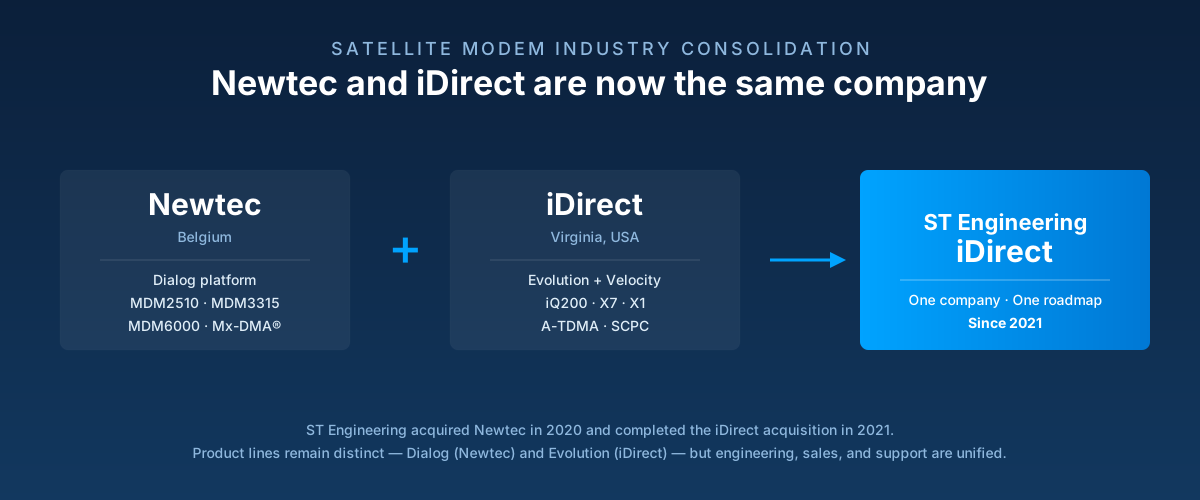
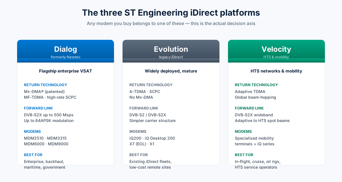
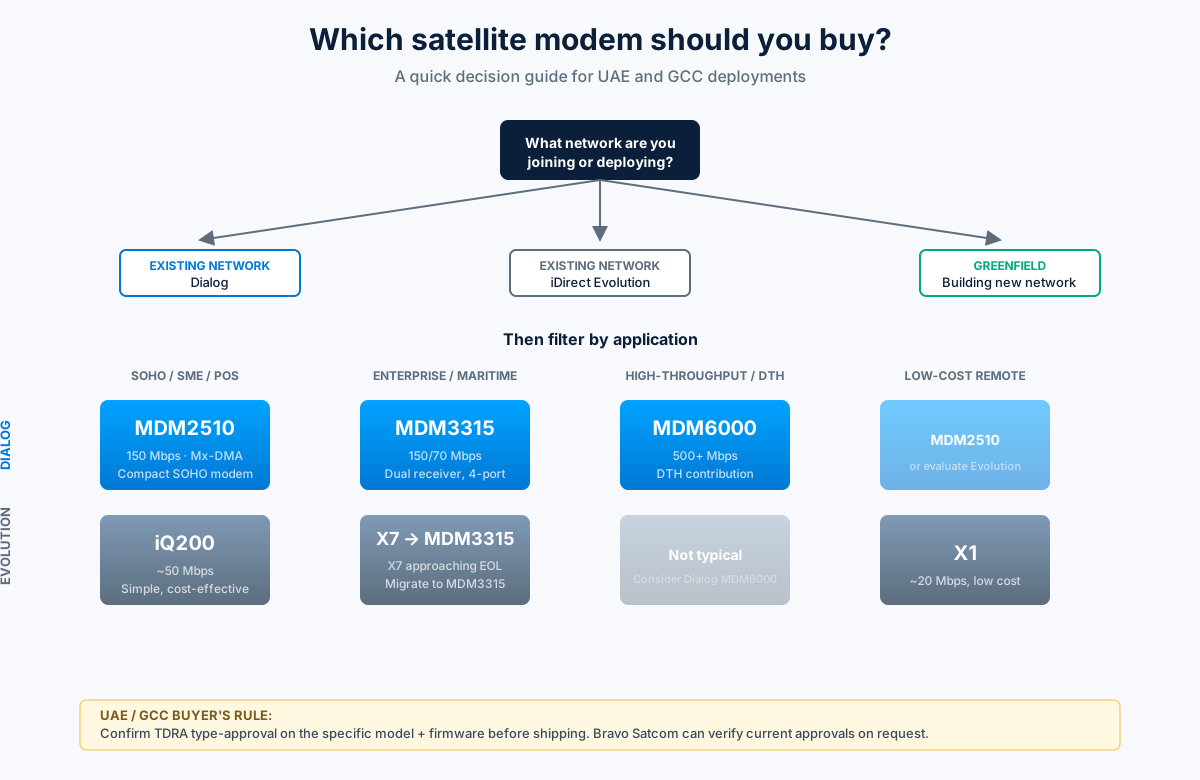
Satellite Modem Vendors: iDirect (ST Engineering) — MDM3315 and Evolution X series support COTM deployments; iQ for LEO/MEO. Viasat — software‑defined modems for FDMA, MF‑TDMA, and military waveforms. Comtech EF Data — CDM‑840 and Heights platform for SCPC COTM links. Hughes — JUPITER platform‑based on‑the‑move terminals.
How to Choose a COTM System
Platform type dictates antenna form factor: maritime platforms tolerate larger stabilised domes; airborne applications demand low‑profile flat panels; land vehicles balance aperture size against height clearance and vibration requirements.
Throughput requirement determines band and aperture size. Low‑rate telemetry and voice can use L‑band or small‑aperture Ku. High‑definition video surveillance, real‑time operations data, and crew welfare broadband require Ku or Ka HTS with larger apertures.
Latency sensitivity drives orbit selection. Standard data and VoIP work on GEO. Real‑time video conferencing, financial transactions, and tactical applications with tight timing constraints benefit from MEO or LEO.
Security requirements define whether commercial (Ku/Ka) or military (X‑band) spectrum is required, and which waveforms and encryption standards must be supported.
Regional coverage must be confirmed against the intended operating area. Not all satellites cover all ocean areas or remote terrestrial regions equally.
Frequently Asked Questions
Conclusion
COTM systems solve a fundamental operational problem: reliable broadband satellite communications from a platform that cannot stop. From armoured military convoys and offshore supply vessels in the Arabian Gulf to emergency response vehicles and seismic survey trucks operating in remote desert terrain, COTM enables command, control, situational awareness, and crew welfare in environments where terrestrial networks do not reach.
The technology has matured significantly — from expensive custom military programmes to commercially available integrated terminals across Ku, Ka, and now LEO bands. ESA flat‑panel antennas are driving down cost and form factor while maintaining performance, and LEO constellations are broadening the addressable market.
For organisations in the GCC and MENA region evaluating COTM, the key decisions are platform compatibility, throughput requirements, orbit selection, and — for government and defence applications — waveform and encryption standards. The equipment infrastructure that supports those decisions — BUCs, LNBs, and compatible cabling — is available through specialist satellite equipment suppliers in the region.
Browse BUCs, LNBs, antennas, and IFL cables for COTM and VSAT projects at BravoSatcom — VSAT Equipment. Our team can advise on equipment selection for land‑mobile, maritime, and airborne COTM systems.